![]()
*Note: The back taper relief gound on the anvil is to allow for the overbend required without pinching the material at full closure. *85° minimum anvil angle suggested for all 90° bends). Always grind 2° to 3° more back taper on anvil than the rocker’s angle “A” being used.
Steps to setting a Rotary Bender
1.. Remove return spring(s) and plunger(s) so the rocker can rotate. There is NO NEED to totally disassemble the bender for setting purposes or to remove rocker.
2. Using two pieces of the part material (median thickness preferred), place one piece on the anvil near to but not into the anvil radius (see drawing). Put the bender into approximate position.
3. Keeping the second piece of material flush to the bending obe of the rocker like a feeler gage (moving up and down minorly), set the opening between the tangency of the anvil radius and the bending jaw of the rocker. Be sure your anvil section has more relief than angle A of the rocker 3° is recommended). Tighten bender screws and reassemble springs and plungers, oil lightly.
4. KEY THE BENDER to locate and resist bending pressure.
5. A final, very minor shut height adjustment will remove excess overbend if needed.
CAUTION: Die Setters and Press Operators MUST be instructed that they CANNOT use the exact same adjustment practices for Rotary Benders as they use for Wipe Bending Tools. BENDERS ARE BETTER, but they are also “different”. See “Trouble shooting” section.
Setting Offset Bends
Bending Offset Bends with a Rotary Bender requires more setting time since you are producing two Bends in a single press stroke. We recommend a two-piece 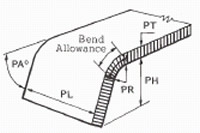 anvil section matched to the jaw of the rocker, usually ground to 90° (See sketch). Offset Bends rarely require any springback allowance! The lower Part Radius (PR2) is most successful when held to 1-1/2 times Part Material Thickness (PT). Smaller radii are possible, but not usually recommended due to tonnage and part consistency concerns.
1. Without the lower anvil insert in place, set the first leg of the Offset Bend per normal Rotary Bender setting instructions.
2. Add the lower anvil insert and set the second leg of the Offset at the desired Part Height (PH). The lower anvil should have a generous radius to allow the first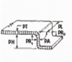 bent leg to be formed as far as possible before the second leg starts. (See sketch)
3. It is often necessary to reset or shim the bender closer to the anvil, and/or reposition the lower anvil insert, up or down, to “fine tune” the Offset Bend to required part tolerances.
Offset Bend Notes:
A. A pad (built-in or independent) is normally required to act as a spacer to adjust the rocker diameter to the desired part height, while maintaining retention of the rocker. The pad distributes holddown pressure over the top of the part.
B. Additional holddown or pilots may be required to resist tilting and part movement during bending.
Trouble Shooting
Most problems with benders are easy to fix!
The most common problem is not enough back taper relief on the anvil or insert that the rocker forms material around. Often the bender is improperly located wither too close or too far away from the anvil or insert. Check the “K” dimension as per the setting instructions.
Bender Adjustment
You can vary overbend by minor shut height adjustments. Progressive dies are usually best adjusted by moving the bender slightly in (closer to anvil) for more overbend, or out (away from anvil) for less overbend. The standard 87° rocker only has 3°overbend.
Critical – Once the holddown jaw is parallel to the material, ALL adjustments must be in or out. The rocker can be reground to add overbend . . .
| Problems | Possible Reasons | Solutions |
|
1. UNDERBENT |
1A. Bender is set “too open” |
Reset bender per instructions. |
2. OVERBENT |
2A. The bender is set too tight |
Reset bender per instructions. |
3. HOOK |
3A. Material is being “trapped” at the tangency (pinch point) |
Reset bender per instructions. Check anvil |
4. EXCESSIVE MARKING |
4A. Bender is set too tight |
Reset bender per instructions. |
5. SADDLE IMPRINTING ONTO THE PART |
5A BENDER IS SET MUCH TOO DEEP! |
|
 | ||